Description
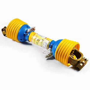
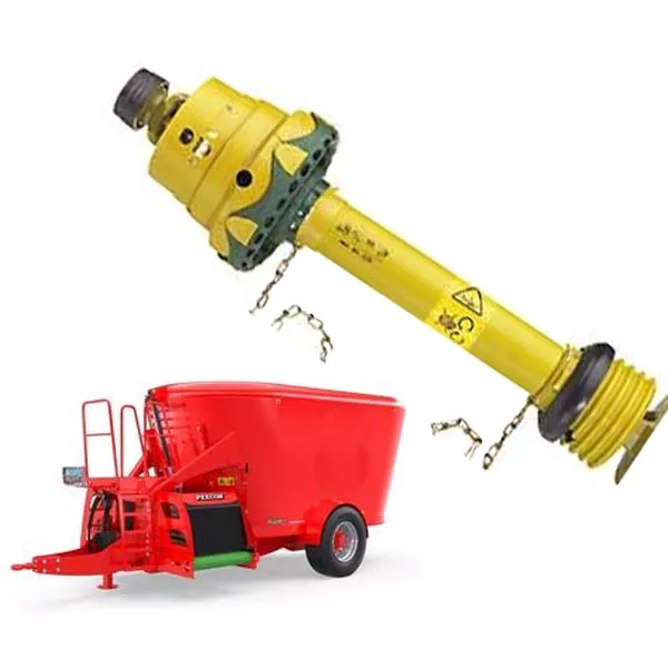
PTO Shaft for Vertical Feed Mixers

PEECON Vertical Feed Mixers Models
| MODEL | CAPACITY | # OF AUGERS | MIN. POWER REQUIREMENTS |
|---|---|---|---|
|
865
|
865 CFT
|
2
|
95 hp
|
|
1100
|
1100 CFT
|
2
|
135 hp
|
|
1300
|
1300 CFT
|
3
|
180 hp
|
|
1500
|
1500 CFT
|
3
|
200 hp
|
Our research indicates most tractors use 1.750-20 spline, and the input shaft on most models is 1.750-6 spline.
Other combinations are available.
We can also supply all the parts for the feed mixer.
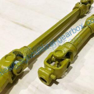
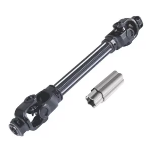
Main Shaft: CAT 6 Constant Velocity
|
|
|||
|---|---|---|---|
|
Tractor Output Shaft
|
Complete CV Assembly Part Number (no implement yoke) |
CV 1/2 shaft Part Number |
Implement Half (2500) Part Number |
| 540rpm
1.375‘’×6 spline |
392206
|
392206-HALF
|
2500-IMPLEMENT-HALF
|
| 1000rpm
1.375‘’×21 spline |
392221
|
392221-HALF
|
2500-IMPLEMENT-HALF
|
| 1000rpm
1.750‘’×20 spline |
392220
|
392220-HALF
|
2500-IMPLEMENT-HALF
|

Mixer Input Requirements
| Part Number | Model | Diameter | Splines | Torque | |

2500 Series Automatic Cutout Clutches |
134467 | K64/24 | 1.750 | 20 | 3500nm |
| LAF20250MDAL67 | K64 | 1.750 | 20 | 2500nm | |
| 135416 | K64/24 | 1.375 | 6 | 2700nm | |
| 135362 | K64/24 | 1.750 | 6 | 2700nm | |
| 135986 | K64/24 | 1.750 | 20 | 2700nm | |

2500 Series Shear Bolt Yokes |
BTL67214810A | KB61 | 1.375 | 21 | |
| BTL67385610A | KB61 | 1.375 | 6 | 2920nm | |
| 355272 | KB61/2 | 1.375 | 6 | 2920nm | |
| 4250104 | KB61/2 | 1.375 | 6 | 2920nm | |
| BTL67205610A | BTL | 1.750 | 20 | 2920nm | |
| 4250105 | KB61/2 | 1.750 | 20 | 2920nm | |
| BTL67345610A | KB61 | 1.750 | 6 | 2920nm | |
| 338427 | KB61/2 | 1.750 | 6 | 2920nm | |
| 392340 | KB61/2 | 1.9375 RD | 0.50 KEY |
What size is a PTO shaft?
Whether buying a new implement with a PTO shaft or replacing an old one, most PTO shafts need to be cut to fit the length between the tractor and the implement using it. This is a simple process that we have outlined in the following steps.
- Connect the implement to the tractor’s three-point linkage without connecting the PTO shaft.
- To determine the length of the PTO shaft, it is necessary to measure the distance between the groove on the tractor’s PTO output shaft and the implement’s PTO output shaft.
- Once you have measured, we usually recommend taking an additional 75mm from the PTO shaft as a buffer to facilitate connection. If there is no buffer, it may not allow any movement and damage the universal joint on the PTO shaft, the implement, or the tractor.
 To help explain, we used the following example:
End-to-end length of new PTO shaft = 1000mm.
Distance between the tractor output shaft and implement output shaft=800mm
Additional buffer=75mm
Therefore, to obtain our measurement results, we need to do the following:
PTO shaft length – the distance between the tractor and implement+75mm buffer.
1000mm – 800mm + 75mm = 275mm, which needs to be removed from the PTO shaft.
- The simplest way to cut the PTO shaft to the proper size is to pull it in half so that there are internal and external parts. It is not necessary to remove the plastic cover. In the above example, we need to remove 275mm from the length, so we need to cut 275mm and 275mm steel pipes on the plastic PTO shaft cover and inner and outer parts, respectively. First, measure the required amount on the plastic to cover and mark it with text, then cut off the excess. Then measure the required amount from the steel pipe and cut it with a hacksaw or angle grinder. Repeat this procedure for the other half of the PTO shaft.
- You need to ensure that any burrs on the cut end of the PTO shaft are removed so that the PTO slides correctly. We also recommend applying some grease to both sides of the PTO before reassembly. After reassembling the PTO shaft, you can connect it to the tractor and implement it.
Note: The above information is for reference only. Diesel Machinery is not responsible for any damage or injury to personnel or equipment when measuring and cutting the PTO shaft.